Bio-Inspired Quadruped Spiderbot
| Links: Final Report (PDF) | Isaac Lab Training | ROS2 Workspace
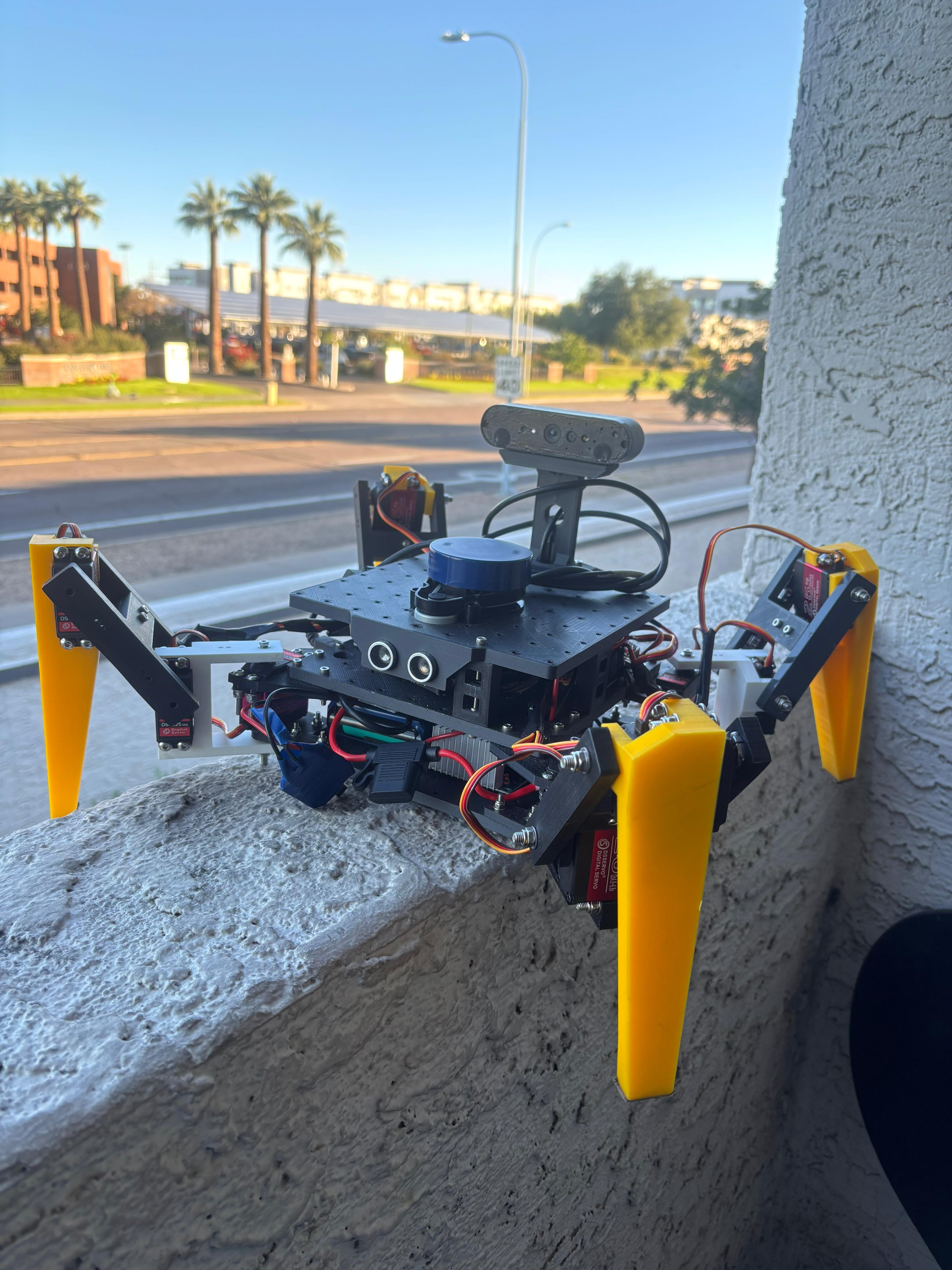
A low-cost 12-DOF quadruped robot with forward kinematics gait control, integrated SLAM, and YOLOv8 object detection. Parallel simulation studies exploring CPG-RL approaches using Van der Pol oscillators.
A ** 12-DOF quadruped spiderbot** with two parallel development tracks: a deployed teleoperated system using forward kinematics with predefined gait patterns, integrated with LiDAR-based SLAM and YOLOv8 object detection; and simulation studies exploring Central Pattern Generator-Reinforcement Learning (CPG-RL) approaches using Van der Pol oscillators for bio-inspired locomotion control.
Stack: ROS2 Humble · Arduino Mega · Raspberry Pi 4 · YDLiDAR X2 · MPU9250 IMU · DS3225 Servos · Isaac Lab · RSL-RL (PPO) · Van der Pol CPG · SLAM Toolbox · YOLOv8.
What’s in this project?
Deployed System
- 12-DOF quadruped platform with custom 3D-printed mechanical design
- Forward kinematics-based gait control with predefined crawling patterns
- 6-DOF motion commands: forward, backward, lateral, and yaw movements
- LiDAR-based SLAM for real-time mapping and localization
- YOLOv8 object detection for environment awareness
- Teleoperated control over ROS2 network
Simulation Studies
- CPG-RL architecture learning to modulate Van der Pol oscillator parameters
- Comparison studies: Pure RL, Hopf CPG, and Van der Pol CPG approaches
- 4096 parallel environments in NVIDIA Isaac Lab
- Multi-task training with domain randomization
- Sim-to-real transfer challenges documented
Gallery
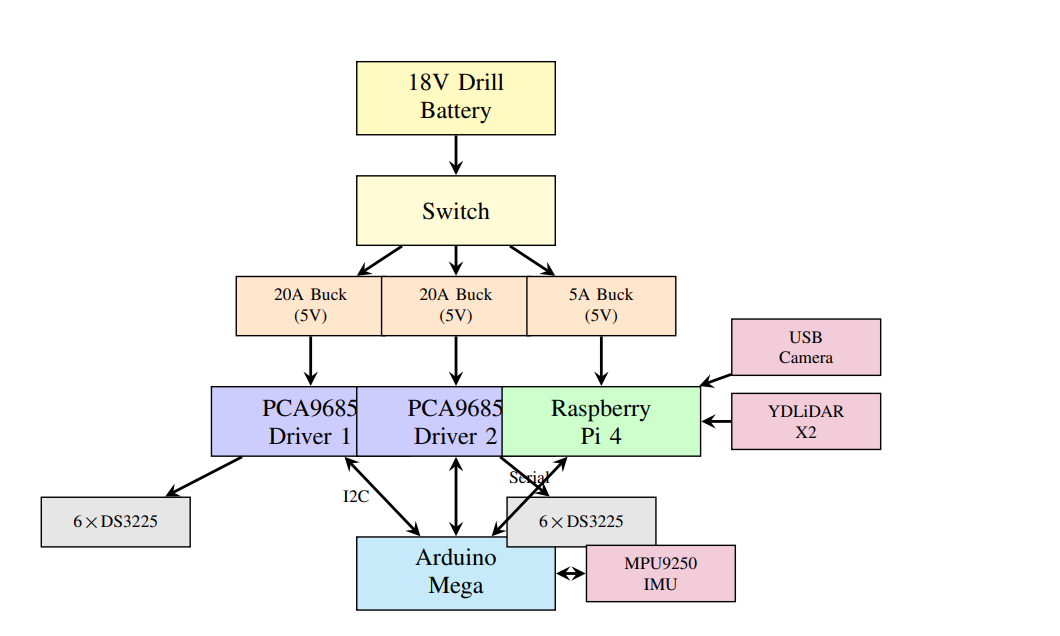 Hardware architecture: Raspberry Pi 4, Arduino Mega, PCA9685 drivers, and sensor integration.
System Design
Mechanical Architecture
The quadruped spiderbot features a symmetric configuration with four legs, each consisting of three joints:
- Coxa (hip rotation): Controls leg orientation
- Femur (thigh elevation): Controls leg lift
- Tibia (knee flexion): Controls foot placement
Total: 12 degrees of freedom
Design Challenges & Solutions
1. Structural Design:
- Initial designs cracked under component weight at joint locations
- Solution: Increased infill percentage and switched to gyroid infill pattern for improved strength-to-weight ratio
- Complete robot resize required to accommodate all components
2. Actuation System:
- DS3225 digital servos (25 kg·cm torque @ 6V) for each joint
- Two PCA9685 16-channel PWM drivers via I2C bus
- Challenges encountered:
- PWM calibration critical for accurate angle mapping
- Excessive current draw during static poses
- Motor disengagement under excessive load
- Careful load distribution required for stability
3. Power System:
- 18V 10Ah lithium-ion drill battery (stripped down)
- Power distribution via three buck converters:
- Two 20A buck converters (5V): Power six servos each
- One 5A buck converter (5V): Powers Raspberry Pi 4
Robot Specifications: | Parameter | Value | |———–|——-| | Total Mass | 3.2 kg | | Degrees of Freedom | 12 (3 per leg) | | Servo Model | DS3225 | | Servo Torque | 25 kg·cm @ 6V | | Battery | 18V 10Ah Li-ion | | Control Frequency | 50 Hz |
CAD Assembly Video
CAD assembly process showing the 3D-printed components and servo integration.
Electronics and Computing Architecture
Hierarchical Control System:
1. Low-Level Control (Arduino Mega 2560):
- Real-time servo control and IMU data acquisition
- Gait engine with predefined joint angle sequences
- PWM signal generation through PCA9685 drivers
- MPU9250 IMU data collection and streaming
- Serial command interface for motion commands
2. High-Level Control (Raspberry Pi 4):
- Ubuntu Server 22.04 headless with ROS2 Humble
- YDLiDAR X2 data acquisition
- USB camera feed processing
- ROS2 node communication with remote workstation
- Serial communication with Arduino for gait commands
- ROS_DOMAIN_ID=7 for network communication
Deployed System: Forward Kinematics Gait Control
Kinematics Approach
Due to the complexity of inverse kinematics for a 12-DOF system with joint offsets, the deployed system uses forward kinematics only. Each leg is modeled as a 3-DOF kinematic chain, and foot positions are computed from joint angles to verify reachable workspace and joint limits.
Gait Implementation
Gaits are implemented as predefined sequences of joint angles stored in lookup tables:
- Crawling gait: 75% duty factor with predefined swing/stance phases
- Motion commands: Forward, backward, left, right, yaw-left, yaw-right
- Smooth transitions: Timed interpolation between gait sequences
SLAM Integration
ROS2 Nodes:
ydlidar_ros2_driver: Publishes/scantopicslam_toolbox: Performs online SLAM, publishing/maprobot_state_publisher: Broadcasts TF transforms
Object Detection
YOLOv8 model processes the USB camera feed for real-time object detection, enabling environment awareness during teleoperation.
Hardware Demo: Walking on Ground
Spiderbot executing forward kinematics-based crawling gait with 75% duty factor.
Simulation Studies: CPG-RL Approaches
In parallel with the deployed system, we conducted simulation experiments exploring learning-based locomotion control in NVIDIA Isaac Lab with 4096 parallel environments.
Pure Reinforcement Learning (Initial Attempt)
First approach: Direct joint control with PPO
- Action space: 12D continuous (direct joint positions)
- Observations: IMU data (no joint encoders)
Problems encountered:
- Unnatural joint angles beyond comfortable ranges
- Jerky, discontinuous motion
- “Cheating” behaviors (dragging body, hopping on two legs)
- Complete failure during hardware deployment attempts
This motivated exploration of structured approaches.
CPG-Based Approaches
Hopf Oscillators
Initial CPG implementation used Hopf oscillators, but the purely sinusoidal waveforms produced overly smooth, unnatural gaits without distinct swing/stance phases.
Van der Pol Oscillators
Following prior work, we implemented Van der Pol oscillators: \[\ddot{x} - \mu(1 - (x/A)^2)\dot{x} + \omega^2 x = 0\]
where:
- $\mu = 2.5$ controls nonlinearity
- $A$ is amplitude
- $\omega = 2\pi f$ is angular frequency
Advantages:
- Non-sinusoidal waveforms with distinct swing/stance phases
- Adjustable duty cycle via $\mu$ parameter
- Sharp phase transitions
Hybrid CPG-RL Architecture
The final simulation architecture has the RL policy learn CPG parameters rather than direct joint commands:
Action Space (17D):
- Frequency (1D): 0.3–2.5 Hz (shared)
- Amplitudes (12D): 0.0–0.7 rad (per joint)
- Phase offsets (4D): ±1.0 rad (per leg)
Observation Space:
- Actor (52D): Commands, history, IMU data, CPG phases, previous actions
- Critic (76D): Actor observations + privileged joint state (training only)
This asymmetric actor-critic design allows the actor to be deployed without joint encoders while the critic uses privileged information during training.
Training Results
Using RSL-RL (PPO implementation), training over 4096 parallel environments produced:
- Smooth forward, lateral, and yaw motions in simulation
- Multi-task training (random commands) outperformed curriculum learning
- Domain randomization applied: mass ±30%, friction ±25%, actuator parameters ±25%
Isaac Sim Locomotion Videos
Forward Motion:
Lateral & Yaw Motion:
Yaw Rotation (Slow):
Sim-to-Real Challenges
Initial deployment attempts failed due to:
| Challenge | Impact |
|---|---|
| Heavy mass | 3.2 kg approaches servo torque limits |
| Servo dynamics | Compliance, backlash, and latency not modeled |
| Friction mismatch | Simulation $\mu=1.0$ vs. real $\mu\approx0.6$ |
| CPG frequency | Required reduction from 2.0 Hz to 1.3 Hz |
| IMU noise | MPU9250 drift and noise not matched in simulation |
| Open-loop control | No joint encoders to measure actual positions |
Sim-to-real transfer of the CPG-RL policy remains future work.
Results
Deployed System Performance
The forward kinematics teleoperated system successfully demonstrates:
- ✅ Stable crawling gait execution
- ✅ 6-DOF motion commands (forward, backward, lateral, yaw)
- ✅ Real-time SLAM map generation
- ✅ Object detection via YOLOv8
- ✅ Reliable remote operation over ROS2
Simulation Results Summary
| Approach | Motion Quality | Stability | Sim-to-Real |
|---|---|---|---|
| Pure RL | Unnatural | Poor | Failed |
| Hopf CPG | Smooth | Moderate | Not tested |
| VDP CPG-RL | Natural | Good | In progress |
Challenges and Lessons Learned
Mechanical Design
- Component weight must be considered from initial design
- Gyroid infill patterns significantly improve joint strength
- Iterative prototyping essential for proper component housing
Servo Motor Challenges
- PWM-to-angle calibration critical for multi-DOF coordination
- Static current draw can exceed driver ratings
- Load distribution prevents motor disengagement
Control System Insights
- Forward kinematics sufficient when IK complexity exceeds implementation resources
- Predefined gaits provide reliable baseline for teleoperation
- Open-loop control fundamentally limits precision without encoders
Sim-to-Real Gap
- Hobby servos behave significantly differently from simulated actuators
- Domain randomization alone insufficient for low-cost hardware
- Sensor-minimal designs require careful IMU noise modeling
Future Work
- Complete sim-to-real transfer of CPG-RL policy
- Integration of joint encoders for closed-loop control
- Extension to rough terrain locomotion
- Autonomous navigation combining SLAM with learned locomotion
- Improved servo dynamics modeling in simulation
- Enhanced domain randomization for low-cost hardware
Code Availability
The source code for this project is publicly available:
- Isaac Lab Training: spiderbot - Contains simulation environment, CPG-RL training configurations, and trained policies.
- ROS2 Workspace: spiderbot.ws - Contains ROS2 packages for robot control, SLAM integration, teleoperation, and sensor processing.
Acknowledgments
This work was conducted at the School for Engineering of Matter, Transport and Energy at Arizona State University under the supervision of Dr. Hamidreza Marvi.